Maintenance, inspection and test of Sino Mechanical IBOP
Maintenance of Sino Mechanical IBOP
Check the internal blowout preventer daily to see if it is working properly and leaking; lubricate the required parts with grease. Because the internal structure of the valve body has grooves and shoulders, it is particularly prone to wear and fatigue cracks. These internal defects will cause increased bending and tensile stresses.
It is very important to check the damage of the internal blowout preventer every week;
Every year or after 3,000 working hours, it is recommended to perform magnetic particle inspection on the outer surface of the valve body to check for damage or cracks. If the above defects exist, it may need to be replaced. Shallow pits or rust damage less than 1.6mm are acceptable. Large damage or cracks must be replaced.
Every 5 years or more than 15,000 hours, it is recommended to perform magnetic particle inspection on the entire surface of the component (including the inner surface) to check for damage or cracks depending on different working conditions. If the above defects exist, it may need to be replaced. Shallow pits or rust damage less than 1.6mm are acceptable. If the diameter is greater than 1.6mm, it needs to be replaced.
Disassembly and assembly Sino Mechanical IBOP
Disassembly:
1. Rotate the valve core to the open position;
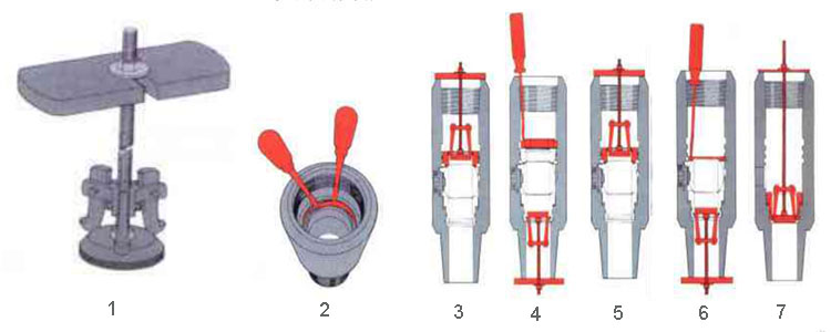
2. Remove the hole retaining ring (Figure 2) and the support ring (Figure 3);
3. Use the assembly tool (Figure 1) to squeeze the wave spring (Figure 4), and then remove the upper split retaining ring; Use the assembly tool to pull out the upper valve seat (Figure 5):
4. Use the assembly tool to squeeze the wave spring (Figure 6) and remove the lower split retaining ring;
5. Rotate the valve core to the closed position and then remove it;
6. Press the handle device (operating handle, handle sleeve, cross slide and seal) into the valve body hole and remove it;
7. Remove the lower valve seat (Figure 7);
8. Remove the upper end O-ring and wave spring;
Assembly: (lubricate all parts before assembly):
1.Insert the lower seat assembly (lower seat, O-ring and wave spring) into the valve body, and then use the assembly tool to position it;
2.Press the handle assembly from the valve body hole into the valve body hole, and then rotate it to the closed position;
3.Rotate the valve core to the closed position and then insert it;
4.Install the upper O-ring and its protective gasket;
5.Install the lower split gasket in the lowest groove;
6.Install the upper seat using the assembly tool:
7.Install the split gasket and support ring, and then release the assembly tool;
8.Install the retaining ring for the hole.

Inspection and testing of Sino Mechanical IBOP
Safety instructions
1. The test of the internal blowout preventer is a high-pressure test, which requires the test personnel to have the corresponding qualifications, certain technical knowledge, operating skills and safety knowledge.
2. Before the test, the test device should be fully inspected to confirm that there are no obvious defects in the parts and connections of the device.
3. During the test, the test personnel shall operate and observe the test device in an appropriate position to avoid personal injury due to high-pressure leakage and part damage.
Inspection and test
1.Inspection and test rules
The internal blowout preventer shall be inspected and tested one by one, and those with unqualified items shall not be used.
2. Inspection items and technical requirements The inspection items and technical requirements of the internal blowout preventer include:
3. Appearance inspection
Visually inspect the inside of the internal blowout preventer, and there shall be no burrs, iron filings and other dirt. If necessary, the inside shall be purged with compressed air when the ball valve is half open.
Repeatedly turn the ball valve, and there shall be no jamming.
Check and verify the relevant marking content to meet the requirements of the technical documents.
4. Thread inspection
Use a thread gauge to check the connection thread to meet the requirements of the relevant technical documents.
5. Test items, methods and technical requirements The test medium is clean water, and an appropriate amount of rust inhibitor can be added to the test medium as needed. When connecting the test device, pay attention to the connection threads at all places, which must not be less than the specified number of threads. If the number of threads exposed on the pipeline is too large, reconnect or replace the parts.
After connecting the test device, turn the ball valve of the internal blowout preventer to a half-open and half-closed position. Open the relief valve, start the pump to inject the test medium, and exhaust the air in the pipeline. When it is confirmed that the air in the pipeline is completely exhausted, close the inlet relief valve and the outlet relief valve in turn.
Start the pump to increase the pressure to the maximum test pressure, stop the pump for 5 minutes, and observe the leakage of the test device pipeline. After there is no abnormality, slowly open the outlet relief valve to completely release the system pressure.
NO. | Test items | Test method | Technical requirements |
1 | No-load torque | Open the outlet relief valve, repeatedly open and close the ball valve 5 times, record the opening torque and closing torque, record the switching torque, and calculate the torque average. | 5-1/4 internal blowout preventer |
2 | External leakage | Turn the ball valve to the open position, start the pump to fill the liquid, close the outlet relief valve, increase the system pressure to the rated working pressure, stop the pump for 5 minutes, and observe the leakage at the adjusting screw. | Switch torque: 20~60 Nm |
3 | Low pressure seal test | Open the outlet relief valve, turn the ball valve to the closed position, increase the system pressure to 1.7Pa, stop the pump and maintain the pressure for 3 minutes, and observe and record the pressure drop of the inlet pressure gauge. Reduce the pressure to zero, restart the pump, increase the system pressure to 1.7Pa, stop the pump and maintain the pressure for 10 minutes, and observe and record the pressure drop of the inlet pressure gauge. | No leakage. |
4 | High pressure seal test | Open the outlet relief valve, turn the ball valve to the closed position, increase the system pressure to the rated working pressure, stop the pump and maintain the pressure for 3 minutes, and observe and record the pressure drop of the inlet pressure gauge. Reduce the pressure to zero, restart the pump, increase the system pressure to the rated working pressure, stop the pump and maintain the pressure for 10 minutes, and observe and record the pressure drop of the inlet pressure gauge. | Pressure drop is not more than 0.5MPa |
5 | Static pressure test | Turn the ball valve to half-open and half-closed state, start the pump to fill with liquid, close the outlet relief valve, increase the system pressure to 1.5 times the rated working pressure, stop the pump and maintain the pressure for 3 minutes. Reduce the pressure to zero, restart the pump and increase the system pressure to 15 times the rated working pressure, stop the pump and maintain the pressure for 10 minutes | Pressure drop is not more than 0.7MPa. |
Cleaning after the test of Sino Mechanical IBOP
Put the ball valve of the internal blowout preventer to a half-open and half-closed position (open about 45°), drain all the test media, and blow dry the internal parts with compressed air.
Put the internal blowout preventer in an oil pan filled with hydraulic oil, repeatedly open and close the ball valve 5 times, take it out and drain all the hydraulic oil, put the ball valve in the open position, wipe the inner surface, and install the thread guard.
Supplier of IBOP
Sino Mechanical Equipment is a supplier of IBOP, located in Shengli Oilfield, the second largest oilfield in China, and is committed to providing high-quality oil drilling equipment and oil processing equipment to the world.


