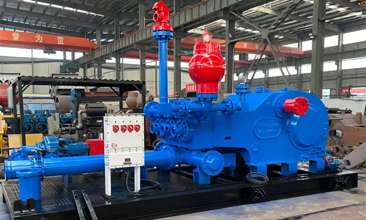
Assembly of F-500/F-800/F-1000 drilling mud pump produced by Sino Mechanical
Preparation of the power end of Sino Mechanical mud pumps
Before being sent to the oil field, the F series mud pumps have been fully assembled and tested. The lubricating oil of the power end is discharged. The following operations and inspections should be performed before the pump is operated:

1. Lubrication of the power end of Sino Mechanical mud pumps
Before adding lubricating oil, open the inspection door on the cover to check whether the lubricating oil in the inner cavity of the power end may be condensed, open the pipe plugs on both sides of the pump, release the accumulated oil and flush the inner cavity of the power end. Then, according to the requirements of the lubricating oil on the nameplate nailed to the frame, inject a certain brand and amount of lubricating oil into the power end.
After the pump has been running for 15 minutes, check the oil level again, stop the pump for about 5 minutes to stabilize the oil, and check the oil mark. Usually, more than 10 liters (3 gallons) of lubricating oil must be added to supplement the oil stagnant in the crosshead and the frame cavity.
2. Installation of the intermediate tie rod and packing box of Sino Mechanical F-500 pumps
Remove the packing box and rotate the pump so that the crosshead is at the front end of the stroke. Thoroughly clean the front of the crosshead and the end face of the intermediate tie rod, then install the positioning boss of the intermediate tie rod into the crosshead hole, tighten the bolts, and finally lock it with wire.
After thoroughly cleaning the surface of the guide cylinder and the packing box, install the O ring and install the packing box, and connect the joint on the return oil pipeline. Tighten the packing box according to the following torque. And connect the return oil pipeline.
The packing box assembly includes: double lip oil seal, oil seal cup, locking spring, and O ring. The method of installing the assembly is as follows:
1) Remove the pressure spring from the double lip oil seal and install it on the intermediate tie rod. With the main lip facing the power end, install the pressure spring on the sealing lip and slide them into the packing box.
2) Install the oil seal ring and O ring on the intermediate tie rod and then install them into the packing box hole.
3) Install the O ring into the groove of the packing box.
4) Install the lock spring.
Note: It is necessary to ensure that the pressure spring does not slip when the intermediate tie rod is severely scratched. Apply light oil to the surface of the intermediate tie rod to make the packing box assembly easy to install.
3. Installation of the intermediate tie rod and packing box of Sino mechanical F-800/1000 pumps
Remove the packing box and mud guard plate and rotate the pump so that the crosshead is at the front end of the stroke. Thoroughly clean the front of the crosshead and the end face of the intermediate tie rod, and then install the positioning protrusion on the intermediate tie rod into the crosshead hole. Tighten the bolts and finally lock with wire.
Clean the connecting end face of the mud guard plate and the frame, install the gasket and screws, and tighten the screws.
Clean the mud guard plate hole and end face, clean the outer surface and flange surface of the packing box, apply light oil to the outer surface of the packing box and install the O-ring, install the packing box on the mud guard plate, and tighten the bolts.
The packing box assembly includes: double lip oil seal, oil seal ring, O ring, and locking spring. The installation method is as follows:
(1) Remove the spring from the double lip oil seal and seal the oil seal to the outside of the crosshead tie rod with the main lip facing the power end.
Then install the spring on the oil seal lip and slide them into the packing.
(2) Install the O ring into the oil seal ring and install it on the tie rod together, and then install it into the packing box hole.
(3) Install the O ring into the groove of the packing box.
(4) Install the double lip oil seal in the same way as step (1).
(5) Install the locking spring.
(6) Note: It must be ensured that the pressure spring will not slip out of the groove of the oil seal lip when the crosshead tie rod is severely scratched. Apply light oil to the tie rod to make the packing box assembly easy to install.
Spray pump assembly of Sino mechanical mud pump
The spray pump assembly consists of a spray pump, a water tank, a spray pipe, etc. Its function is to flush and cool the liner piston during the operation of the pump.
During all use times, proper attention must be paid to ensure that the coolant is fully supplied to the liner and piston. Interruption of the coolant will immediately cause damage to the piston rubber parts and liner.
The F series drilling pump uses a fixed nozzle. It includes: a fixed frame, a steel pipe and a nozzle installed on the frame, which sprays the coolant on the liner and piston area. Adjust the water supply of the manifold to ensure that the sprayed liquid flow is directly shot on the piston.
The coolant is output from the water tank to the manifold located on the left (right) wall of the frame through a spray pump. The regulating valve supplies as much water as possible to spray on the liner, so as not to splash on the packing box and the middle tie rod. Otherwise, a small amount of water will return to the power end and contaminate the lubricating oil.
The coolant returns from the front cavity of the frame to the sedimentation chamber of the water tank. When the coolant overflows through the filter, solid phases such as mud and water are precipitated, and foreign matter is blocked by the filter.
Check the cleanliness of the coolant frequently, clean and flush the water tank as needed, and replace the coolant. The contaminated liquid will cause early wear of the piston and liner, or block the nozzle due to the increase of sand particles.

Assembly of hydraulic end parts of Sino mechanical mud pump
1.Valve and valve seat
Remove the three valve covers, three cylinder heads and plugs, and thoroughly clean the machined surfaces of the hydraulic end (clean with high-quality solvent).
Confirm that each valve seat hole must be very clean and dry (no dirt, grease, rust inhibitor, etc.). Use emery paper to grind off all burrs on the surface, and the sandpaper should be circulated along the valve seat hole.
Clean and dry the valve seat thoroughly, install the suction and discharge valve seats into the valve cavity hole, and use a copper rod or copper hammer to knock the valve seat to make it in place. Install the valve body spring and parts. Install the liquid baffle at the end of the middle tie rod.
Check the liner hole again to make sure it is clean and free of foreign matter to ensure that the liner and the hydraulic end form metal-to-metal contact. The presence of foreign matter may cause the liner to "lift up", causing early damage to the liner and piston.
Thinly apply grease or oil to the hydraulic end liner hole. Then push the liner into the hole until its shoulder is in metal-to-metal contact with the shoulder of the hydraulic end.
2.Piston rod
Clean the piston and piston rod to ensure that they are free of burrs and scratches. Install the O ring into the sealing groove of the piston, gently install the piston onto the piston rod, and be careful not to let the O ring slip out of the groove. Tighten the piston rod nut with the following torque value.
F-500 500N.m(368.1bs)
F-800/1000 1625~2165N.m(1200~1600ft.1bs)
Apply grease to the inner hole of the liner and the outer surface of the piston, check the tie rod and the end of the piston rod to make sure they are clean and free of burrs, push the piston rod into the liner, keep the rear of the piston rod liner centered, and use hardwood or special tools to drive the piston into the liner. Note that when the piston rod approaches the middle tie rod, the positioning boss at the end of the piston rod must not be damaged, and the piston rod must be supported so that it enters the positioning hole.
3.Piston rod clamp
The clamp is processed as a whole and divided into two. Both pieces are marked with matching numbers and connected with a chain. These two parts with the same matching number should be used as a set, clamped on the piston end flange, and tightened. The torque values are as follows:
F-500 135N.m (100ft.lbs)
F-800 135N.m (100ft.lbs)
F-1000 215N.m (160ft.1bs)
If the piston rod and clamp are new, the opening of the two half clamps of the clamp has a gap of more than 5.5mm, so that the piston rod end face forms a good metal-to-metal connection. When worn, the two half clamps will tend to get closer. If there is no gap, the clamp does not work, and the clamp should be replaced.
4.Cylinder lifter and lower valve guide
Install the sealing ring at the rear of the liner and assemble the liner in place. Push the cylinder lifter into the hydraulic end, align the lower hole of the cylinder lifter with the lower valve cavity hole, install the guide on the lower valve stem through the lower hole of the cylinder lifter, and rotate the wing on the guide back and forth. Press down the guide and press the spring until the guide can rotate 1/4 turn, so that it can be seated under the cylinder lifter. Install the lower valve guide stopper through the eye of the lower valve guide, rotate the card to the right, so that the valve guide is stuck on the cylinder lifter and locked. Sometimes the middle of the card must be bent more or less so that when the handle of the card is stuck in the right position, the clamp clamps the guide tightly.
5.Cylinder head
Install the outer sealing ring in the hydraulic end hole facing the cylinder lifter, and install the cylinder head plug into the hydraulic end. Apply grease to the matching threads of the cylinder head, then install it on the pump head and tighten it with the booster rod supplied with the pump.
Liquid leaks through the drain hole, indicating that the seal is damaged or the cylinder head is loose. Do not plug the drain hole. Because this will "puncture" the cylinder head thread and cylinder head flange thread once the liner seal fails.
6.Valve cover
Install the valve cover seal ring into the hole, apply grease to the sealing part and threaded part of the valve cover, and tighten the valve cover with a force rod and a chuck.
Discharge manifold of Sino mechanical Mud pumps
The flange of the discharge manifold is 5" (127mm). After removing the flange and the sealing gasket, weld the flange to the discharge pipeline (the user selects the welding method). Tighten the flange connection bolts with a torque of 1625~2165N.m (1200~1600ft.1bs). Tighten the bolts and nuts in a cross manner. If the other end of the manifold is not connected to the pipeline, use a blind flange to seal it.
Auxiliary pipeline of Sino mechanical mud pumps
The auxiliary pipeline can be installed on the discharge manifold opposite to the discharge end. This manifold can be connected to the air bag and is equipped with two side outlets connected to the shear pin safety valve and pressure gauge respectively. The auxiliary pipeline and the discharge manifold are flange-connected. Before installation, the sealing steel ring groove on the flange must be thoroughly cleaned, the steel ring must be placed, and the flange thread must be tightened. The tightening torque is 1625N.m. To ensure that the sealing steel ring connector is tightened evenly, a cross-cross method must be used for tightening.
A shear pin safety valve is also installed on the auxiliary pipeline to prevent rapid emptying when the pump pressure exceeds the specified value to ensure the safety of the mud pump. The shear pin safety valve must be installed so that it can directly contact the mud. No type of gate is allowed to be installed between the discharge pipeline and the safety valve. Lead the discharge end of the safety valve directly to the mud pool with a pipe. This pipeline should have as few turns as possible. It is not allowed to put the safety The discharge end of the valve is led to the suction pipe of the pump by a pipe.
The shear plate of the shear pin safety valve is engraved with the mark of each level of working pressure. When adjusting the pressure, just insert the safety pin into the corresponding hole according to the given pressure. Note that only one safety pin can be inserted into the shear plate. If the liner size changes, the safety valve pressure must be adjusted accordingly. Remember not to use an Allen wrench, welding rod or other materials to replace the safety pin, as this will affect the pressure value of the safety valve.
Before installing the air bag, thoroughly clean the gasket and groove. After installing the air bag, tighten the nut with a torque of 1020N.m. To ensure uniform tightening, tighten it in a cross-cross manner.
Before starting the pump, pre-inflate the air bag, and the inflation pressure must not exceed 2/3 of the pump discharge pressure. The air bag should be filled with nitrogen or air, and flammable and explosive gases such as oxygen and hydrogen are not allowed.