Description
Overview of Accumulator Unit
A BOP accumulator unit is one of the critical components for preventing blowout in drilling and workover operations.
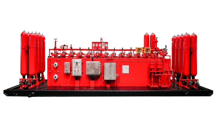
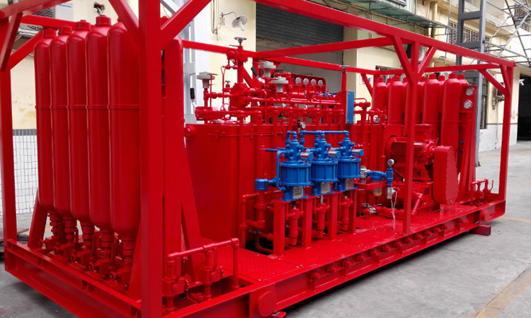
A BOP accumulator unit (also known as BOP Control System, Koomey Unit, BOP Control Unit, Pressure Control Units, BOP Closing Units) is a unit used to hydraulically operate the opening and closing of Single Ram BOP, Double Ram BOP, Annular BOP, HCR, hydraulic throttle valve, kill valve and other hydraulic equipment.The BOP accumulator units for BOP stacks is a very important equipment which come as skid mounted units with control panel.
The BOP accumulator units is specifically engineered in order to assure reliable control of the BOP stack with adequate reserve for continuous operation under emergency conditions. It is necessary to accurately operate and maintain the hydraulic control system.
The primary purpose of BOP accumulator units is to supply hydraulic power to the BOP stack in order to close/open BOP stack for both normal operational and emergency situation.
With the development of oilfield safety operation, BOP accumulator unit (also known as BOP Control System, Koomey Unit, BOP Control Unit, Pressure Control Units, BOP Closing Units) are widely used in oilfield. Proper use and maintenance of accumulator unit are very important.
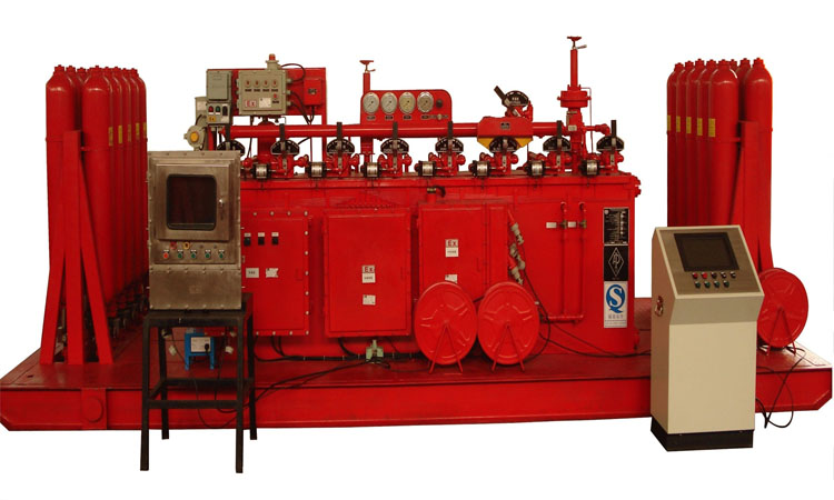
Accumulator unit consists of remote console, driller console, auxiliary console, air pipe cable (except electric control type), pipe rack, high-pressure manifold, protection room, etc.. Accumulator unit can prevent blowout and eliminate spillage flow and achieve rapid well killing and other main functions.
The main components of the FKQ series BOP Control System are remote console (generally equipped with protection room), driller's console, air pipe cable, hydraulic pipeline (hose line or pipe bracket, closed elbow and other hardware) Pipeline, to be specified when ordering).
The main components of the FK series BOP Control System are remote control console (generally equipped with a protection room), hydraulic pipelines (hard pipelines such as hose lines or pipe bends, closed elbows, etc., which need to be specified when ordering).
Accumulator unit is designed, manufactured and inspected in accordance with API Spec. 16D and it can be divided into two types: Electrical type FKDQ series and Pneumatic type FKQ series.
According to customer requirements, the functions that can be added to some models include alarm device, nitrogen backup system and pressure compensation device
Note: The composition of the BOP Control System is customized according to customer requirements.
Features of Accumulator Unit
1. The remote console is equipped with two independent power sources.
2. According to the configuration of the Accumulator Unit, electric oil pumps, pneumatic oil pumps or manual oil pumps with different displacements are provided.
3. The accumulator unit is designed to meet the control requirements of closing all blowout preventer groups and opening hydraulic valves. The accumulator system is designed so that when one or a group of accumulators fails, the capacity loss is not more than 25% of the total capacity, and accumulators with ASME inspection marks can be provided.
4. The control device with pneumatic manual pressure regulating valve has the function of remote pneumatic pressure regulation. When the air source suddenly fails, the control pressure can automatically return to the initial setting value. There is a backup pressure source interface on the control manifold of the remote console, which can introduce a pressure source when needed.
5. A nitrogen backup system can be provided as needed to provide emergency auxiliary energy for the control manifold. When the accumulator and/or pump unit cannot provide enough motive fluid for the control manifold, a nitrogen backup system can be used to provide high pressure gas to the manifold to shut down the blowout preventer. The nitrogen backup system can also provide an emergency gas source for the driller's floor and auxiliary consoles in case of emergency.
6. The remote console is equipped with two independent power sources. According to different configurations, electric pumps with different displacements can be provided, and the maximum theoretical flow rate can reach 460L/min. Equipped with electric pumps of various specifications, it can start with low air pressure and ensure the normal operation of the system even in the event of a power failure. work; can be configured with a large displacement pneumatic oil pump of 50:1.
7. The accumulator unit has sufficient high-pressure liquid reserves to meet the control requirements for closing all blowout preventer groups and opening hydraulic valves. If any group (one) of accumulator bottles fails, the loss of the total fluid volume shall not exceed 25%.
8. The hydraulic device with pneumatic manual pressure regulating valve has remote pneumatic pressure regulating kinetic energy, and its pressure regulating characteristic is reverse pressure regulation. When the air source suddenly fails, the control pressure can automatically return to the initial setting value. And according to the special requirements of users, motor pressure regulating valves (ie TR valves) can be provided
9. There is an excuse for a backup pressure source on the control manifold of the remote console, which can introduce a pressure source when needed, such as a nitrogen backup system. The nitrogen backup system provided by our company can provide emergency auxiliary energy for the control manifold. A nitrogen backup system can be used to supply high pressure gas to the manifold to shut down the blowout preventer when the accumulator and pump unit cannot supply sufficient motive fluid to the control manifold.
10. Alarm devices can be configured according to customer requirements. Monitor the accumulator pressure, gas source pressure, and mailbox liquid level. When the above parameters exceed the set alarm limit, an audible and visual alarm signal can be given on the remote console and the driller console to provide the operator with action. measure.
11. Pressure compensation device can be configured according to customer requirements. When this device is installed on the pipeline controlling the annular blowout preventer, the fluctuation of pipeline pressure will be absorbed immediately, thereby reducing the wear of the rubber core of the annular blowout preventer, and at the same time, it will quickly reset the rubber core after passing through the joint, ensuring Drilling safety.
12. The auxiliary console can be configured according to the customer's requirements. In order to facilitate the control of the remote console, the FKQ series control device can be equipped with an auxiliary console. The auxiliary control console adopts pneumatic control, and is connected with the remote control console through the air pipe cable, so that the remote control console can be controlled at the driller's console or the auxiliary control console.
13. In order to adapt to field work in cold areas, thermal insulation room and air conditioner, as well as oil tank heating, air pipe and cable electric heating, explosion-proof electric heating plate and explosion-proof air-conditioning device can be configured according to customer requirements.
Applications of Accumulator Unit
1. During drilling, the Accumulator Unit is mainly used to control the main equipment of wellhead blowout preventer or hydraulic blowout valve.
2. The Accumulator Unit is composed of remote console, drilling console, auxiliary console, air pipe cable electric control type, pipe bent frame, high pressure manifold, protection room, etc. The main functions are to prevent blowout, eliminate overflow and realize rapid well killing.
3. The Accumulator Unit adopts a separate installation structure, which improves the safety strength of the Accumulator Unit and facilitates the disassembly and maintenance of the Accumulator Unit and the unloading valve.
4. The drilling console has the characteristics of compact structure, reasonable layout, convenient operation and clear marking.
5. The remote console is equipped with electric and pneumatic dual power sources, and it is also equipped with an accumulator for the Accumulator Unit to ensure normal operation even in unexpected situations.
6. The power source is equipped with an automatic control device, and the hydraulic system is set according to the double industrial pressure overload protection, so the whole machine is easy to operate.
7. The accumulators of the Accumulator Unit are divided into four groups to ensure that when a single accumulator or a group of accumulators fail, there is still 75% of the accumulator capacity for the normal operation of the system.
Accumulator Unit Consist of
1. Remote Console
The remote console is composed of base, oil tank, pump group, accumulator group, manifold, various valves, instruments and electric control box, etc. The main function of the remote console is to generate high-pressure control fluid from the pump set and store it in the Accumulator Unit. When it is necessary to open and close the blowout preventer, the high-pressure control fluid from the Accumulator Unit is distributed to each control object (blowout preventer) through the three-position four-way rotary valve of the manifold.
Features of the remote console are:
(1) . Equipped with two sets of independent power sources. FKQ series is equipped with electric oil pump and pneumatic oil pump, FK series is equipped with electric oil pump and manual oil pump. Even in the case of power failure, the system can be guaranteed to work normally.
(2) The Accumulator Unit has sufficient high-pressure liquid reserves to meet the control requirements of closing all BOP groups and opening hydraulic valves. If any accumulator bottle fails, the loss of the total liquid volume of the accumulator shall not exceed 25%, which meets the requirements of API specifications.
(3) Both the electric oil pump and the pneumatic oil pump are equipped with automatic start and stop control devices. In normal work, even if the automatic control device fails, the overflow valve can overflow quickly to ensure the safety of the system.
(4) The opening and closing action of each blowout preventer is controlled by the corresponding three-position four-way rotary valve. FKQ series Accumulator Unit can be used for direct manual reversing or pneumatic remote reversing. FK series Accumulator Unit can only change direction manually.
(5) There is a backup pressure source interface on the control manifold of the remote console, which can introduce a pressure source when needed, such as a nitrogen backup system.
(6) The annular blowout preventer control circuit of FKQ series Accumulator Unit can be remotely adjusted pneumatically, and when the air source suddenly fails, the control pressure can automatically return to the initial set value, which meets the requirements of API specifications.
2. Driller Console
FKQ series Accumulator Unit can be equipped with driller's console. The driller's console is usually installed on the drill floor, so that the driller can easily realize the remote control of the blowout preventer.
Driller console features are:
(1) The working medium is compressed air to ensure safe operation.
(2) The spool function of each pneumatic valve is Y-type, and can be reset automatically, which will not affect the remote control operation of the blowout preventer group on the remote console under any circumstances.
(3) With operation memory function. Each three-position four-way pneumatic rotary valve is respectively connected with a display cylinder. When the rotary valve is operated to the "open" or "close" position, the word "open" or "close" will appear in the display window at the same time. After the handle is reset, the display sign remains unchanged, so that the operator can know the status of the previous operation on the driller's floor.
(4) In order to ensure the reliable and correct operation of the BOP Stack, the rotary valves of the driller’s console adopt a two-stage operation method, that is, firstly, the rotary valve of the air source should be turned to connect the air source, and at the same time, the rotary valve of the driller’s console should be turned to control the rotary valve. The valve can make the corresponding control object act.
3. Air Tube
(1) The air hose is used to connect the air circuit between the remote control console and the driller's console.
(2) The air pipe cable is composed of a sheath and a plurality of pipe cores, with connecting flanges at both ends, which are respectively connected with the remote console and the driller's console, and the connecting flanges are sealed with rubber gaskets.
4. Hydraulic Line
(1) In general, the distance between the remote console and the wellhead BOP Stack is 30m, and a set of hydraulic pipelines should be used to connect them. The connection methods include hard pipeline connection and hose line connection.
(2) Hard pipelines include pipe bends, closed bends, triple bends, etc. The use of hard pipeline connection has the advantages of safety and reliability, but the disadvantage is that it is inconvenient to arrange and install.
(3) The connection of the hose line has the advantages of simplicity and convenience, but attention should be paid to its safety during use.
(4) According to the site conditions, soft and hard pipelines can also be used in combination to give full play to their respective advantages. For example, pipe bends are used for long straight pipelines, and hose lines are used for connection at both ends.
5. Tube Rack
(1) The pipe bracket is specially designed to protect the high pressure control liquid pipeline.
(2) High-pressure oil pipes are installed in the pipe rack according to the number of control objects to connect the remote console with the BOP Stack.
(3) The oil pipes between the pipe racks are connected with quick-change joints, which can be tightened by hammering, which is very convenient. There are baffles at both ends of the pipe rack to protect the quick-change joints from damage during transportation.
(4) The extended lengths of the closed elbows are 2 meters, 3 meters and 4 meters respectively. Each section of the oil pipe is connected by a movable elbow, which is flexible in rotation and very convenient for on-site installation.
(5) The three-bend pipe can be connected with the main body of the blowout preventer, and can also be used to connect the outlet of the remote control console with the pipe bracket.
(6) The two ends of the hose line are generally self-sealing quick connectors, which replace hard pipelines such as pipe bends and closed elbows, and realize the connection between the Accumulator Unit and the blowout preventer.
(7) The connecting threads at both ends of the pipeline are 1 LP (oil pipeline thread GB/T 9253.2-1999, equivalent to NPT1, GB/T12716-1991). The connection between the pipelines generally adopts quick-change joints or quick joints.
6. Alarm System
(1) The remote console can be equipped with an alarm device to monitor the accumulator pressure, air source pressure, oil tank liquid level and the operation of the electric pump. When the above parameters exceed the set alarm limit, the remote console and the driller can sound and light alarm signals are given on the console to prompt the operator to take measures. Operators should use the information provided by the alarm instrument and other instruments to comprehensively analyze the working status of the equipment to ensure the reliable operation Accumulator Unit.
(2) The functions of the alarm device include low accumulator pressure alarm, low air source pressure alarm, low oil tank liquid level alarm, and electric pump operation indication.
7. Nitrogen Backup System
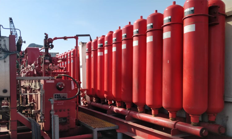
(1) The nitrogen backup system consists of several high-pressure nitrogen cylinders connected to the control manifold, which can provide emergency auxiliary energy for the control manifold.
(2) The nitrogen backup system is connected to the control manifold through isolation valves, check valves and high-pressure ball valves. If the accumulator and/or pump unit cannot provide sufficient motive fluid to the control manifold, a nitrogen backup system can be used to provide high pressure gas to the manifold to shut down the blowout preventer.
(3) The connection method between the nitrogen backup system and the control manifold can prevent the pressure liquid from entering the nitrogen backup system, and the nitrogen gas should be prevented from entering the accumulator circuit during operation.
(4) The nitrogen backup circuit is designed with a discharge control valve to control the discharge of high-pressure nitrogen to prevent high-pressure nitrogen from being discharged into the liquid tank. A backup nitrogen system can also charge the accumulators.
8. Pressure Compensation Device
(1) The pressure compensation device is the supporting equipment of the Accumulator Unit. During drilling, when the drill pipe joint passes through the annular blowout preventer, pressure fluctuations are generated in the hydraulic system.
(2) Install this device on the pipeline controlling the annular blowout preventer, the fluctuation of the pipeline pressure will be absorbed immediately, thereby reducing the wear of the packing element of the annular blowout preventer. At the same time, the packing element of the annular blowout preventer can be quickly reset after passing the joint to ensure drilling safety.
(3) The pressure compensation device is installed in the annular preventer control pipeline of packing element of the annular blowout preventer. In order to ensure the use effect, the device should be installed on the closed oil pipeline close to the annular preventer.
Price of Accumulator Unit
The Accumulator Unit Price will change randomly with factors such as production cost, transportation cost, international situation, exchange rate, market supply and demand of raw materials. Sino Mechanical aims to provide you with high quality and best price Accumulator Unit. If you are looking for Accumulator Unit or Accumulator Unit spares, please kindly contact us to get the latest Accumulator Unit price.
Accumulator Unit Supplier
Sino Mechanical, as a Accumulator Unit manufacturer, has more than 20 years extensive experiences in the performance, application and cost-effective manufacturing of Accumulator Unit. We are global Accumulator Unit supplier. We offer a wide range of drilling equipment and have Accumulator Unit for sale. We also provide OEM services. We design, manufacture, and sell Accumulator Unit for your drilling applications. If you want to know latest Accumulator Unit price, don’t hesitate to contact us anytime. We will get back to you within 24 hours.
Specification
Technical Specifications of Accumulator Unit
The technical parameters of Accumulator Unit are relatively complex and have various structural forms. In order to help customers order correctly and ensure the configuration of the well control system complies with national standards and API specifications, customers are requested to provide detailed technical information, data and usage requirements as possible when selecting models.
MODEL | NUMBER OF CONTROLLED OBJECTS | ACCUMULATOR UNIT | PUMP SYSTEM DISPLACEMENT | RATED OPERATING PRESSURE OF THE SYSTEM (MPA) | |||
TOTAL VOLUME (L) | AVAILABLE LIQUID VOLUME (L) | INSTALLATION MODE | TRIPLEX PUMP (ML/R) | PNEUMATIC PUMP | |||
FKDQ1920-13 | 13 | 80×24 | 960 | Side / Rear | 80×3 | 120×5 | 21 |
FKDQ1600-14 | 14 | 80×20 | 800 | Side / Rear | 80×2 | 120×4 | 21 |
FKDQ1600-12 | 12 | 80×20 | 800 | Side / Rear | 80×2 | 120×4 | 21 |
FKDQ1600-10 | 10 | 80×20 | 800 | Side / Rear | 80×2 | 120×4 | 21 |
FKDQ1440-14 | 14 | 60×24 | 720 | Side / Rear | 80×2 | 120×4 | 21 |
FKDQ1280-10 | 10 | 80×16 | 640 | Side / Rear | 80×2 | 120×3 | 21 |
FKDQ1280-9 | 9 | 80×16 | 640 | Side / Rear | 80×2 | 120×3 | 21 |
FKDQ1280-8 | 8 | 80×16 | 640 | Side / Rear | 80×2 | 120×2 | 21 |
FKDQ1280-7 | 7 | 80×16 | 640 | Side / Rear | 80×2 | 120×2 | 21 |
FKDQ1200-17 | 17 | 60×20 | 600 | Side / Rear | 80×2 | 120×3 | 21 |
FKDQ1200-9 | 9 | 60×20 | 600 | Side / Rear | 80×2 | 120×3 | 21 |
FKDQ1200-8 | 8 | 60×20 | 600 | Side / Rear | 80×2 | 120×2 | 21 |
FKDQ960-8 | 8 | 60×16 | 480 | Side / Rear | 80×2 | 120×2 | 21 |
FKDQ960-7 | 7 | 60×16 | 480 | Side / Rear | 80×2 | 120×2 | 21 |
FKDQ800-8 | 8 | 40×20 | 400 | Side / Rear | 80 | 120 | 21 |
FKDQ 800-7 | 7 | 40×20 | 400 | Side / Rear | 80 | 120 | 21 |
FKDQ 800-6 | 6 | 40×20 | 400 | Side / Rear | 80 | 120 | 21 |
FKDQ720-7 | 7 | 60×12 | 360 | Side / Rear | 80 | 120 | 21 |
FKDQ 720-6 | 6 | 60×12 | 360 | Side / Rear | 80 | 120 | 21 |
FKDQ 640-6 | 6 | 40×16 | 320 | Side / Rear | 80 | 120 | 21 |
FKDQ 640-5 | 5 | 40×16 | 320 | Side / Rear | 80 | 120 | 21 |
FKDQ 480-5 | 5 | 40×12 | 240 | Side / Rear | 80 | 120 | 21 |
FKDQ 480-4 | 4 | 40×12 | 240 | Side / Rear | 80 | 120 | 21 |
FKDQ320-5 | 5 | 40×8 | 160 | Side / Rear | 60 | 120 | 21 |
FKDQ320-4 | 4 | 40×8 | 160 | Side / Rear | 60 | 120 | 21 |
FKDQ320-3 | 3 | 40×8 | 160 | Side / Rear | 60 | 120 | 21 |
FKDQ240-3 | 3 | 40×6 | 120 | Side / Rear | 60 | 120 | 21 |
FKDQ200-4 | 4 | 25×8 | 100 | Side / Rear | 60 | 120 | 21 |
FKDQ160-3 | 3 | 40×4 | 80 | Side / Rear | 60 | 120 | 21 |
FKDQ150-2 | 2 | 50×3 | 75 | Side / Rear | 60 | 120 | 21 |
FKDQ125-3 | 3 | 25×5 | 62.5 | Side / Rear | 28 | × | 21 |
FKDQ80-3 | 3 | 40×2 | 40 | Side / Rear | 28 | × | 21 |
FKDQ80-2 | 2 | 40×2 | 40 | Side / Rear | 28 | × | 21 |
FKDQ75-2 | 2 | 25×3 | 62.5 | Side / Rear | 28 | × | 21 |
FKDQ63-2 | 2 | 63×1 | 31.5 | Side / Rear | 28 | × | 21 |
FKDQ50-2 | 2 | 25×2 | 25 | Side / Rear | 28 | × | 21 |
FKDQ40-2 | 2 | 40×1 | 20 | Side / Rear | 28 | × | 21 |
FKDQ25-2 | 2 | 25×2 | 12.5 | Side / Rear | 28 | × | 21 |
FKDQ25-1 | 1 | 25×2 | 12.5 | Side / Rear | 28 | × | 21 |

