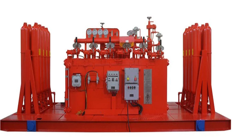
Use and maintenance of blowout preventer control system
Because the surface BOP control device is one of the important equipment of the well control device. Therefore, in order to ensure that the hydraulic control device of the blowout preventer can effectively, reliably and quickly control the blowout in an emergency, technical training must be provided to relevant personnel so that the management and user personnel understand the structure, principles, installation, operation and Maintenance and troubleshooting.

Terms and Conditions
Under normal drilling conditions, the handle positions of each rotary valve on the remote console are: each blowout preventer is in the "open" position, the blowout valve is in the "off" position, and the bypass valve is in the "off" position.
The rotary valve on the driller's console is a secondary operation. When using it, the gas source valve should be pulled first and the corresponding control rotary valve should be pulled at the same time. Since the air piping cable is a long and slender pipeline, it requires a period of response time. You should pause for more than 3 seconds after turning the rotary valve handle to ensure that the corresponding rotary valve in the remote console completes the action. The hydraulic or gas pipelines connecting the control device and the blowout preventer must not pass through the vehicle to prevent crushing. The control system should be comprehensively inspected at least once a week during normal drilling. When approaching or entering the oil or gas reservoir, it is required to be inspected once per shift. The inspection content includes:
1.Whether the fluid level in the fuel tank is normal;
2.Whether electrical components and circuits are safe and reliable;
3.Check whether there is any leakage in the oil and gas pipelines;
4.Whether the automatic start and stop of the pressure controller is accurate and reliable;
5.Whether the displayed value of each pressure gauge meets the requirements:
6.Conduct blowout preventer opening and closing tests in accordance with relevant safety regulations.
maintenance
1.Each oil filter and the filter in the oil port at the top of the oil tank should be dismantled and inspected once a month. The filter should be taken out and cleaned carefully to prevent it from being clogged by dirt;
2.Water separation air filter in the air source treatment component: Open the drain valve at the lower end once a day to drain the sewage accumulated in the cup. Remove the filter cup and water cup and clean them every two weeks. When cleaning, use mineral oil such as gasoline to filter them, and blow them dry with compressed air. Do not clean them with acetone, toluene and other solutions to avoid damaging the cups.
3.The oil mist device in the air source treatment component: Check the wave surface in the cup once a day. Pay attention to replenishing and replacing the lubricating oil in time. If the oil is not dripping smoothly, it should be disassembled and cleaned.
4.Regularly check the nitrogen precharge pressure of the accumulator. Check the nitrogen pressure once a week during initial use, and then once a month during normal use. If the nitrogen pressure is insufficient, it should be replenished in time.
5.Checking the nitrogen pressure must be carried out when the accumulator group is completely depressurized. When the hydraulic control device is transported over a long distance, the nitrogen in the accumulator should be reduced to about 1MPa (140psi) to avoid accidents during transportation.
6.Check the liquid level in the fuel tank at any time, regularly open the gate valve at the bottom of the tank to drain the water, check whether there is sediment at the bottom of the tank, and clean the bottom of the tank if necessary.
7.Regularly check the sealing packing of the electric oil pump. The packing should not be too tight as long as there is no obvious oil surge. If the packing is damaged, it should be replaced.
8.When disassembling the pipeline, be careful not to lose the O-ring of the quick connector. After disassembly, these sealing rings should be collected together and properly kept.
9.Wipe the surface of the remote console and driller console frequently to keep them clean, and be careful not to knock off various signs.
10.After each well is drilled, the pressure gauge should be calibrated.
Lubrication instructions
1.Once a week, use an oil gun to add an appropriate amount of grease and mechanical oil to the two nozzles of the rotary valve air cylinder.
2.Check the lubricating oil of the oil mist device once a week. If it is insufficient, add an appropriate amount of mechanical oil or other suitable oil.
3.Check the crankcase lubricating oil level of the electric oil pump once a month. If it is insufficient, add an appropriate amount of mechanical oil or other suitable oil.
4.Once a month, remove the chain guard and check the lubricating oil. If it is insufficient, add an appropriate amount of mechanical oil or other suitable oil.
Troubleshooting
1. There is noise when the control device is running.
There is gas mixed in the system oil.
Reason: Dry operation, circulating exhaust.
Measures: Check whether the accumulator capsule is ruptured and replace it in time.
2.The motor cannot start
Reason: The power supply parameters do not meet the requirements.
Measures: Repair the circuit.
Reason: The electrical components in the electric control box are damaged or malfunctioned, or the fuse is burned out.
Measures: Repair the electrical control box or replace the fuse
3. After the electric oil pump is started, the system does not increase the pressure or the pressure increases too slowly, and the sound is abnormal when the pump is running.
Reason: The liquid level in the fuel tank is too low and the pump is empty.
Measures: Replenish oil.
Reason: The gate valve of the oil suction port is not opened, or the oil filter of the oil suction port is clogged.
Measures: Check the pipeline, open the gate valve and clean the oil filter.
Reason: The pressure relief valve on the control manifold is not closed.
Measures: Close the pressure relief valve.
Cause: Electric oil pump failure.
Measures: Repair the oil pump.
4. The electric oil pump cannot stop running automatically.
Reason: The oil pipe or joint of the pressure controller is clogged or leaking.
Action: Check the pressure controller line.
Reason: The pressure controller failed.
Measures: Adjust or replace the pressure controller
5. The outlet pressure of the pressure regulating valve is too high
Reason: There is dirt on the sealing surface of the sealing ring in the valve.
Measures: Rotate the pressure regulating handwheel to move the sealing box up and down several times to squeeze out the dirt. Disassemble and repair if necessary.
6. The blowout preventer cannot be opened or closed on the driller's console or the corresponding actions are inconsistent.
Reasons: The tube core in the air duct and cable is connected incorrectly, the tube core is broken or blocked, and the sealing ring of the connecting flange is leaked.
Action: Check the air duct and cable.
Sino Mechanical Equipment provides various oil drilling equipment, such as: Annular BOP, Single Ram BOP and Double Ram BOP,BOP Stacks, Accumulator Unit, BOP Control System, Drilling Spools,Choke and Kill Lines, Hose Loops, drilling mud pumps and accessories, etc. It is committed to developing and providing high-quality oil drilling equipment to meet the changing needs of customers and contribute more to the development of the petroleum industry.