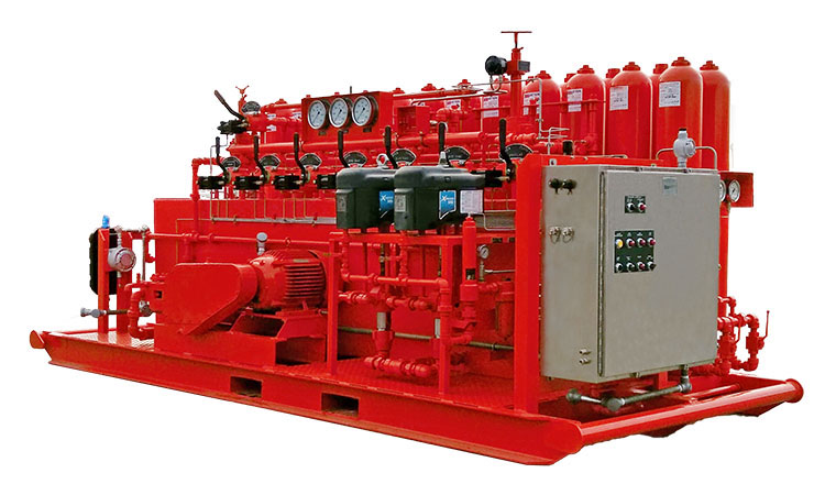
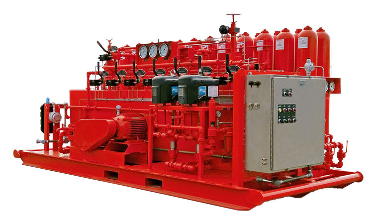
Installation and commissioning of BOP control system
1. When hoisting the remote console in a protective room, four steel wire ropes must be used to cover the four legs of the base. Please pay attention to the stable lifting when lifting. When hoisting the driller's console or pipe rack, the wire rope should be passed through or hooked on the lifting ring for lifting.
2. The remote console should be installed at an appropriate location 30 meters away from the wellhead , and the driller's console should be placed on the drill floor where it is convenient for the driller to operate.
3. Connection of oil pipes
It is recommended to start with the blowout preventer body and connect the pipelines in sequence. This can not only keep the pipelines neatly arranged, but also make it easy to adjust the direction without rework. In addition, all oil and gas pipelines should be purged with compressed air before installation.
4. Connection of air pipeline
When connecting air ducts and cables, pay attention to the direction of the connecting flange, place a seal between the flange surfaces, and tighten the bolts evenly.
The air source of the remote console is connected with a hose, and the air source of the driller's console is connected with a hose. The connection between the hose and the joint must be clamped with a hose clamp to prevent loosening. The hose should be free of aging, cracks and other defects to avoid bursting during use.
5.Power connection
The power supply should be connected in accordance with relevant electrical regulations, and the ground terminal of the electric control box should be reliably grounded to avoid personal accidents.
Before wiring, turn the main switch of the electric control box on the remote console to the "stop" position to prevent the motor from starting immediately after power is supplied and causing an accident.
After the equipment is installed, carefully check whether all connecting pipelines are correct and whether various unions, joints, etc. are tightened before trial operation.

Trial run
Preparations before commissioning are carried out according to the following procedures:
1 .Precharge or check the nitrogen pressure of the accumulators one by one.
2 .Oil tanks filled with oil. It can be added through the refueling port on the top of the fuel tank, or it can be refueled through the suction port of the electric oil pump using the suction pipe. The amount of refueling should be controlled to the mark on the top oil mark on the fuel tank.
3. Lubricate moving parts.
4. Open the accumulator isolation valve, open the pressure relief valve on the control manifold, move the handle of each three-position four-way rotary valve to the neutral position, and the bypass valve is in the "off" position.
5. Turn the main command switch to the "manual" position. After the motor starts, turn the main command switch to the "stop" position. When the motor stops slowly, observe whether its steering direction is consistent with the direction pointed by the arrow above the chain guard. If not, change the phase of the power cord.

Commissioning procedure:
1. Start and stop test of electric oil pump
Turn the main command switch to the "automatic" position. After the electric oil pump runs without load for 10 minutes, close the pressure relief valve on the control manifold to raise the accumulator pressure to 21Mpa (3000psi). At this time, the pump should be able to automatically stop. When automatic stop is not possible, the main command switch of the electric control box can be turned to the "stop" position to stop the pump.
Gradually open the pressure relief valve to slowly relieve pressure on the system. When the oil pressure drops to about 18.9Mpa (2700psi), the electric oil pump should start automatically.
During the above process, check and adjust the pressure controller until the electric oil pump can automatically stop and start. During the boosting process, you should observe whether there is leakage or oil leakage at the joints on the remote console.
2. Pneumatic oil pump start and stop test
When the system uses a pneumatic oil pump, the bypass valve of the liquid-gas switch should be closed, and the air source switch valve leading to the pneumatic oil pump should be opened to make the pneumatic oil pump work. When the accumulator pressure rises to about 21Mpa (3000psi), observe the liquid-gas switch. Whether to cut off the air source to stop the pneumatic oil pump?
Gradually open the pressure relief valve on the control manifold to slowly relieve pressure on the system. When the system pressure drops to about 18.9MPa (2700psi), the pneumatic oil pump should start automatically.
During the above process, check and adjust the liquid-gas switch until the pneumatic oil pump can automatically stop and start. During the boosting process, you should observe whether there is leakage or oil leakage at the joints on the remote console. If there is leakage, repair it.
3. Adjust the pressure regulating valve
During the above pressure increase process, observe whether the outlet pressure value of the pressure regulating valve of the manifold or annular control loop is 10.5Mpa (1500psi), and adjust it if not.
4. Commutation test
The accumulator pressure rises to 21Mpa (3000psi), set the bypass valve on the control manifold to the "off" position, operate the three-position four-way valve on the remote console to change direction, and observe the "open" and "close" actions of the valve Is it consistent with the actual action of the blowout preventer or blowout valve? Operate the gas rotary valve to change direction on the driller's console, and observe whether the "open" and "close" actions of the valve are consistent with the actions of the control object.
In case of inconsistency, check whether the pipeline connection is correct.
Note: During trial operation, an appropriate drill pipe should be inserted into the blowout preventer group to avoid damage to the blowout preventer caused by "zero sealing" (please refer to the blowout preventer operation manual).
5. Relief valve test
Close the accumulator isolation valve on the pipeline, turn the three-position four-way rotary valve to the neutral position, move the main switch on the electric control box to the "manual" position, start the electric oil pump, and the accumulator pressure rises to 23Mpa (3300psi) Check whether the overflow valve at the outlet of the electric oil pump can be fully opened to overflow. After fully opening the overflow, move the main command switch to the "stop" position to stop the electric oil pump. The overflow valve should be completely closed when the pressure is not less than 19Mpa (2700psi).
Close the isolation valve of the accumulator group and move the bypass valve on the control manifold to the "open" position. Open the gas source switch valve, open the bypass valve of the liquid-gas switch, start the pneumatic oil pump, increase the pressure of the manifold to 34.5Mpa (4900psi), and observe whether the manifold overflow valve is fully open for overflow. After fully opening the overflow, turn off the air source and stop the pneumatic oil pump. The overflow valve should be completely closed when the pressure is not less than 28.5MPa (4000psi).
If necessary, the relief pressure of the relief valve should be adjusted.
6. Pneumatic pressure regulation test of annular blowout preventer
Turn the handwheel of the annular blowout preventer gas manual pressure regulating valve downward to set the outlet pressure of the valve to 10.5Mpa (1500psi).
Turn the handle of the distribution valve on the remote console to the "driller's console" position, then adjust the pneumatic pressure regulating handwheel on the driller's console and observe whether the reading of the annular blowout preventer pressure gauge on the driller's console changes. , is it consistent with the pressure gauge reading on the remote console?
Turn the distribution valve handle to the "remote console" position, adjust the pneumatic pressure regulating handwheel on the remote console, and observe the reading of the annular blowout preventer pressure gauge.
Check the oil tank level
If there is too much oil leakage during the above adjustment process and the tank liquid level is too low, the oil should be replenished, but it is not advisable to replenish too much to prevent the accumulator group oil from overflowing when it returns to the tank.
Sino Mechanical Equipment provides various oil drilling equipment, such as: Annular BOP, Single Ram BOP and Double Ram BOP,BOP Stacks,Accumulator Unit, BOP Control System, Drilling Spools,Choke and Kill Lines, Hose Loops, drilling mud pumps and accessories, etc. It is committed to developing and providing high-quality oil drilling equipment to meet the changing needs of customers and contribute more to the development of the petroleum industry.


